If you purchased our Harmony One replacement LCD and the installation did not go as planned, there are many different symptoms that can occur due to installation error. Below is a list of the most frequent problems we’ve seen:
If you are experiencing any of the problems above, you may be able to fix it with a little troubleshooting:
Inspect all ribbon cable pins carefully to ensure that there are no obvious bridges and all pins are flat and in contact with the board. Even when everything looks good from the top, the most frequent installation error we’ve seen is leaving part of the prior LCD’s ribbon cable still attached to the pads on the board. This is more common when ChipQuik de-soldering alloy is not used, or when used, not allowed to detach all of the old ribbon. Soldering the new ribbon to portions of the old will prevent a good solder connection from being made and will result in many of the symptoms described above.
- The remote does not power-on at all anymore.
- The remote powers-on in Safe Mode.
- The remote powers-on, but the LCD does not light up at all.
- The LCD presents with a ‘white screen’ and never displays images.
- The LCD powers-on correctly when the battery is installed, but displays a ‘white screen’ on subsequent ‘wake-up’.
- The LCD is rendering partial images.
- There is a reddish/purple horizontal stripe across the bottom 3rd of the LCD. This is an easy fix! Just remove the protective plastic film that protects the LCD. The stripe is on the film, not the LCD!
If you are experiencing any of the problems above, you may be able to fix it with a little troubleshooting:
- First, make very sure that you have installed the LCD on the GIN PA7.4 version of the PCB. The LCD will not work correctly on the PA7.2 board. If you have confirmed that you have the 7.4 version of the board, then you should make one additional check - This is very rare, but we have seen a few instances where a 7.4 PCB is a ‘hybrid’ build, where a 1st Generation LCD was actually installed by Logitech and a critical component (called a logic gate) was removed from the board to support the 1st Gen LCD. Please review this picture of the location of the component and, if it is not present on your 7.4 board, then the replacement LCD will not work correctly and you should contact us immediately for guidance.
- If the LCD did not render correctly on the first power-on test, then try a couple of additional power-on tests. Sometimes, there is some image corruption left in the video memory in the CPU and this needs to be re-initialized.
- If the backlight is not going on (LCD is dark), then inspect the solder connections that are at Pin 19 and 20. These are the power and ground connections for the backlight.
- If the remote is only presenting with a ‘white screen’, then inspect most of the pins in the middle of the ribbon, as these are the data and command pins. Any obvious bridges or lifted leads will create this problem.
Inspect all ribbon cable pins carefully to ensure that there are no obvious bridges and all pins are flat and in contact with the board. Even when everything looks good from the top, the most frequent installation error we’ve seen is leaving part of the prior LCD’s ribbon cable still attached to the pads on the board. This is more common when ChipQuik de-soldering alloy is not used, or when used, not allowed to detach all of the old ribbon. Soldering the new ribbon to portions of the old will prevent a good solder connection from being made and will result in many of the symptoms described above.

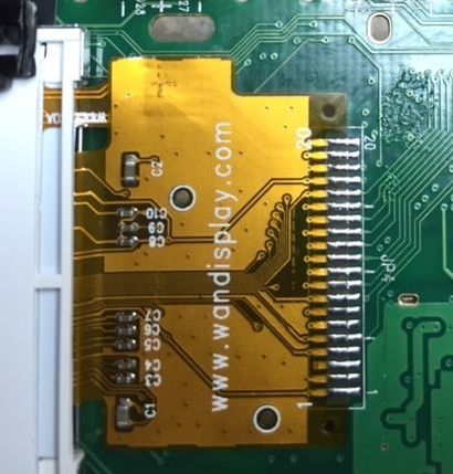
For reference, we've provided a picture of what the finished product should look like. If your work does not appear like this (or close to it), you may want to try adding a bead of flux and swiping each pin with fresh, clean solder. However, if there is already evidence of burned flux (from too much heat or dwelling too long), or the joints are very dull, there may be some risk is reworking the joints. You can always send us a close-up picture of the work and we will review it and try to provide additional guidance and instruction. If you just want to get your Harmony One up and running again, we do offer a Re-Installation Service, which is fairly priced and will include another LCD for no additional cost, assuming the current module cannot be re-installed. Note that there may be an up-charge if there is significant damage found to the board (lifted or missing pads, etc).
Of course, customers want to know if they possibly got a bad module. Although extremely rare, we have seen a few LCD modules fail a short time after installation. However, in these small number of cases, the initial installation was always successful, with the module working perfectly. In all cases we've seen, when an LCD is not working correctly when first installed, it has been due to installation error or an incompatible board. Prior to shipping, each module is thoroughly tested using our LCD testing jig (see video below). Each module is tested for power-on, rendering characteristics, back-light distribution, color temperature, 'wake from sleep' and 'wake from cradle'. Please contact us if you have had difficulty. We are always happy to help!